Regarding the electrical systems in different appliances, clarification is absolutely important. This is particularly true for the YFK2456 blow motor wiring diagram, which is an indispensable instrument for everyone handling blow motors in industrial machines, cars, or HVAC systems. Knowing this wiring diagram benefits maintenance and troubleshooting as well as guarantees correct installation. This article will investigate the importance of the yfk2456 blow motor wire diagram, its components, how to interpret it, and useful applications, thereby enabling both beginners and experts to negotiate more easily.
What is the YFK2456 Blow Motor Wire Diagram?
Complete schematic showing the electrical connections and components linked with a specific blow motor is the yfk2456 blow motor wire diagram. Blow motors are absolutely essential in heating, ventilation, and air conditioning (HVAC) systems as well as in many different automotive applications. This wiring schematic has much important information about wire arrangement, terminal locations, and the types of connections needed for the motor to run as intended. Clear visual depiction helps technicians to prevent errors and guarantee proper motor wiring.
Importance of Wire Diagrams in Electrical Systems
In maintenance and electrical engineering, wire diagrams—such as the yfk2456 blow motor wire diagram—are indispensable. They provide a road map for learning difficult wiring systems, therefore facilitating component and connection identification. Access to a thorough wiring diagram will save time and minimize mistakes for anybody working on electrical systems—in an HVAC unit, an automobile, or industrial machinery. It enables professionals to confidently complete repairs or installs and more successfully solve problems, therefore enhancing system dependability and efficiency.
Key Components of the YFK2456 Blow Motor Wire Diagram
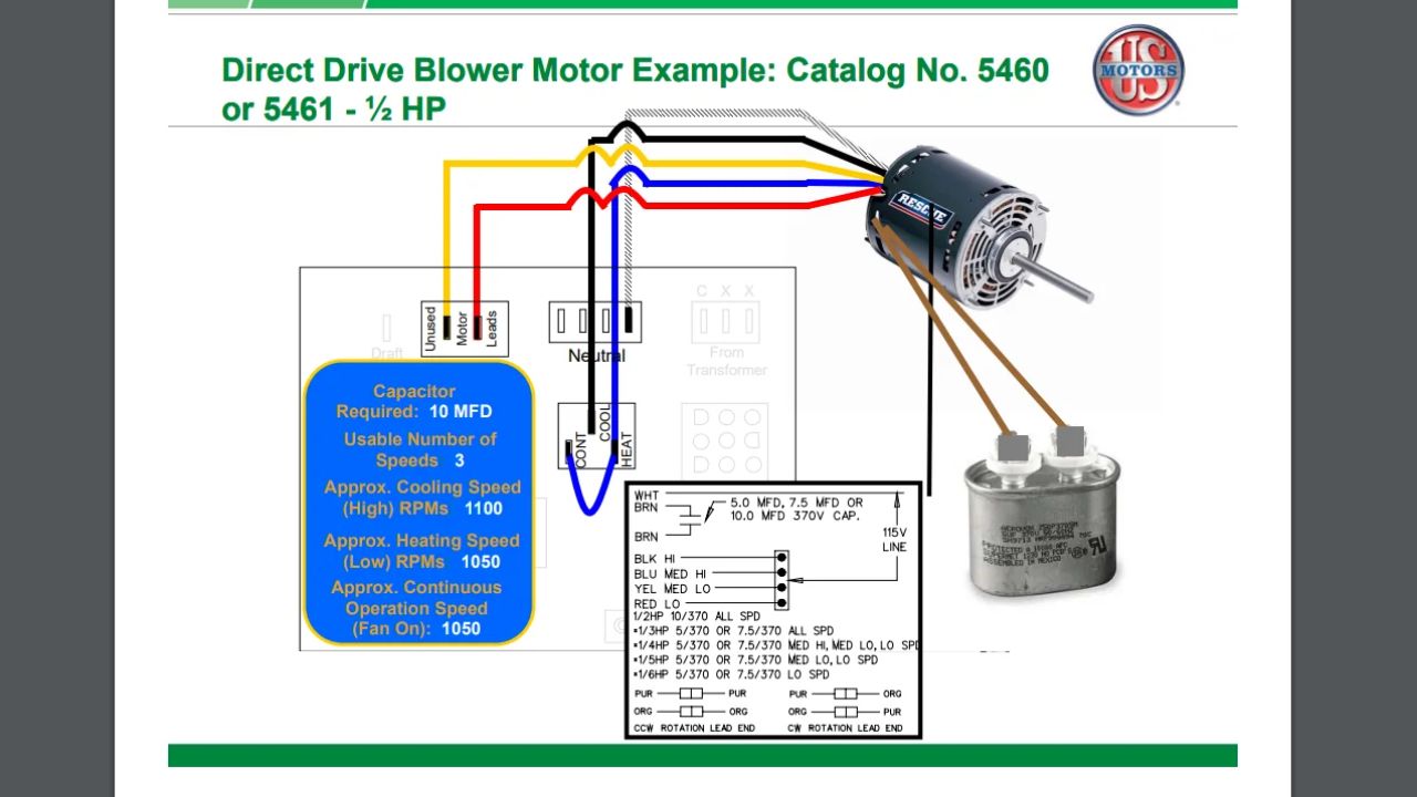
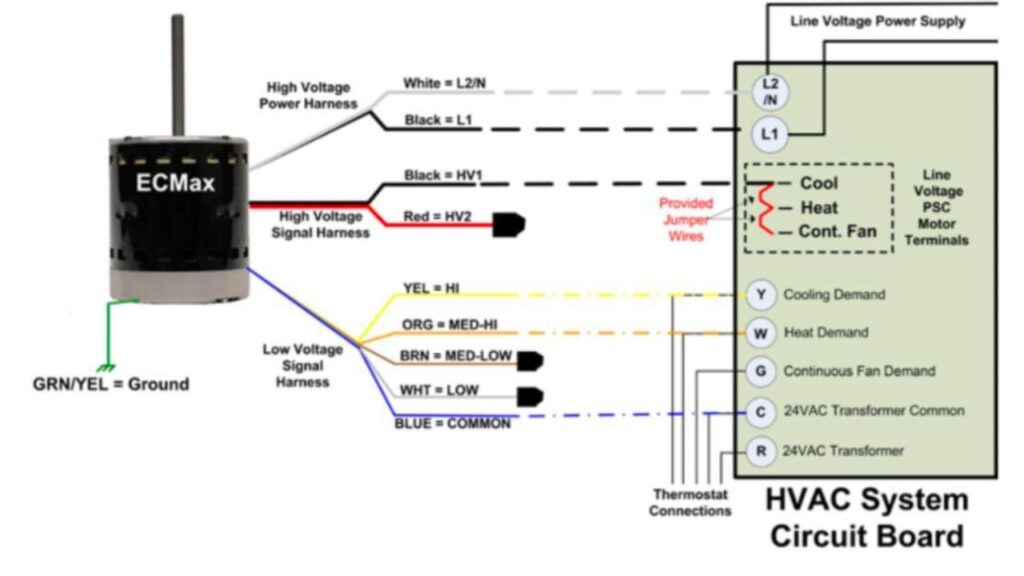
Identification of the main components of the yfk2456 blow motor wire diagram helps one to completely understand it. Usually, the schematic shows several electrical components like the blow motor, power supply, switches, and connections. Every element has labels that help to define its purpose inside the system. The graphic also frequently shows wire colors, which let technicians quickly find connections. Accurate interpretation of the diagram and use in practical situations depend on an awareness of these elements and their functions.
How to Read the YFK2456 Blow Motor Wire Diagram
Though at first intimidating, reading the yfk2456 blow motor wire diagram gets easier with repetition. Start by becoming acquainted with the diagram’s symbols. Every symbol matches a specific electrical component; the lines linking them show current-carrying cables. From the power supply to the blow motor, follow the diagram’s flow while noting any switches or connectors encountered. Breaking up the diagram into smaller pieces helps one to better troubleshoot or install the system by understanding how each component interacts.
Common Applications of the YFK2456 Blow Motor Wire Diagram
Mostly in HVAC systems and automotive engineering, the YFK2456 blow motor wiring schematic has uses in many other disciplines. Blow motors are crucial for circulating air and temperature regulation in HVAC systems, hence the wire diagram is very important for installation and repairs. Blow motors in automobiles assist control cabin air flow, therefore guaranteeing passenger comfort. This figure might also be helpful in industrial environments when ventilation or cooling blow motors are employed. Your capacity to deal with these systems efficiently will be much improved by knowing how to interpret and utilize this wiring diagram.
Troubleshooting with the YFK2456 Blow Motor Wire Diagram
Troubleshooting electrical problems is among the most useful applications for the YFK2456 blow motor wiring diagram. A blow motor’s failing to run as expected makes the diagram a useful tool for spotting possible issues. Following the connections described in the schematic will help technicians rapidly identify malfunctioning motors, damaged switches, or broken wires. By cutting the time spent identifying problems, this methodical approach lets faster fixes possible and helps to minimize downtime. Learning to use the YFK2456 wiring diagram for troubleshooting can help you be much more effective as a technician.
Safety Precautions When Working with Blow Motors
Working with electrical systems, especially those involving the YFK2456 blow motor wiring diagram, safety should always be the first concern.Before beginning any work, ensure the power supply is off to prevent short circuits or electrical shocks. Also very important is wearing appropriate PPE, such as gloves and safety glasses. Check your connections against the diagram twice to avoid mistakes handling wires. Following these safety precautions will assist you to lower risks and offer a safe workplace when completing electrical repairs.
Differences Between Wire Diagrams and Schematics
Especially with the yfk2456 blow motor wire diagram, one must understand the variants between schematics and wire diagrams. Although both help to show electrical connections, they do it in quite different ways. A wire diagram offers a simple graphic depiction of how components are connected by concentrating on the actual wire structure and connections. By contrast, a schematic diagram—often employing abstract symbols—emphasizes the functional links between components. Whether you are fixing current systems or installing new equipment, knowing the variations will enable you to select the suitable diagram for your particular requirements.

Resources for Accessing the YFK2456 Blow Motor Wire Diagram
Thanks to several internet sites, getting at the yfk2456 blow motor wire diagram has gotten simpler. Usually found easily available for consumers, manufacturers include wiring diagrams in their websites or in product manuals. Furthermore, great sites to discover common schematics and assistance from other technicians are electrical forums and groups. By means of community assistance and shared expertise, using these resources not only offers you the required schematics but also improves your understanding of electrical systems.
Best Practices for Documenting Your Own Wire Diagrams
Making your own wire diagrams might be rather useful if you deal regularly with electrical systems. When recording your schematics, take into account best standards to guarantee usability and clarity. Accurate component and connection representation depends on consistent symbols and unambiguous labeling. Keeping a consistent layout will also help to prevent misunderstanding. Furthermore improving understanding and simplifying your diagrams includes color-coding for cables. These techniques can help you design efficient wiring diagrams that others and yourself will find helpful references.
The Future of Wire Diagrams in Electrical Engineering
The future of wire diagrams—including the yfk2456 blow motor wire diagram—probably will alter as technology develops as well. Software and digital technologies are enabling simpler creation, sharing, and modification of wire diagrams. Support of 3D modeling and simulation might potentially become more common, enabling engineers to see electrical systems in fresh perspectives. These technologies will improve our capacity to design and troubleshoot complicated electrical systems, therefore optimizing the work of technicians.
Difference Table
| Feature/Aspect | YFK2456 Blow Motor Wire Diagram | General HVAC Wire Diagrams | Automotive Wire Diagrams | Electrical Schematic Diagrams |
| Purpose | Specifically illustrates blow motor connections | Shows various HVAC components | Details automotive wiring layouts | Represents functional relationships |
| Detail Level | High detail for specific wiring | Moderate detail for systems | Varies, often detailed | Low detail, focuses on functionality |
| Symbols Used | Specific symbols for motors and connections | Standard HVAC symbols | Automotive-specific symbols | Abstract symbols for components |
| Common Applications | HVAC systems, industrial blowers | General HVAC installations | Vehicle electrical systems | Circuit design and analysis |
| User Experience | Designed for technicians with some prior knowledge | Accessible for general users | Often requires automotive knowledge | May require engineering expertise |
| Troubleshooting Guidance | Provides specific wiring guidance for motors | General troubleshooting tips | Specific to automotive issues | Functional troubleshooting methods |

Conclusion: Mastering the YFK2456 Blow Motor Wire Diagram
Ultimately, everyone dealing with blow motors in different applications must have a basic knowledge of the yfk2456 blow motor wire diagram. This schematic helps users easily negotiate difficult wiring layouts, therefore facilitating installation, troubleshooting, and maintenance. You may improve your electrical work by knowing its elements, understanding how to interpret it properly, and using it in useful situations. The YFK2456 blow motor wiring diagram will always be a valuable tool in your toolbox as you keep honing your abilities to negotiate the complex realm of electrical systems.
FAQs
1. Does the Thermostat Control the Blower Motor?
Indeed, regulating the blower motor of your HVAC system depends critically on the thermostat. The blower operation on your thermostat—either “Auto” or “On”—determines its fan setting. In “Auto” mode the blower only moves warm or cool air whether your home is warm or cold. The blower works constantly in “On” mode, therefore preserving air circulation even in cases of non-active heating or cooling system operation. Knowing these levels will enable you to maximize the comfort and energy economy of your house.
2. Which Thermostat Wire Controls the Blower?
Blower fan control in most HVAC systems is accomplished by the G or G1 wire. This wire triggers the blower motor when the thermostat signals heating or cooling, therefore distributing air around your house. If you have a cooling system, the G wire concentrates especially on the fan functioning whereas the Y or Y1 wire usually regulates the compressor. Knowing which wires run your system will help you to guarantee correct operation and troubleshoot.
3. What Does the Purple Wire on a Blower Motor Do?
Control of speed on a blower motor depends critically on the purple wire. Usually a tiny wire from the heater control panel is pulsed to ground to tell the blower motor controller to run at the designated speed. The controller therefore modulates the power sent to the blower motor depending on your heating or cooling requirements. Knowing this will enable you to identify blower motor performance problems.
4. What Color Wire Indicates High Speed on a Blower Motor?
Typically referred to as cooling speed or fan ON continuous speed, the black wire in most blower motor configurations is set aside for high-speed operation. This wire ties to the motor and lets it run at maximum capacity. Whether your system runs on 120V or 230V, appropriate black wire connection guarantees that the motor runs for best air circulation in your house.
5. What is the Function of the Yellow Wire on a Blower Motor in HVAC Systems?
Usually one leg of the 240V power supply in HVAC systems, the yellow wire supplies the blower motor. The wiring schematic of the motor indicates that this wire is absolutely vital as it supplies the motor with continuous power—usually 120V. While the second leg of the 240V power is usually given via the black, blue, or red wires, it should be coupled to the L1 terminal. Correct knowledge of these connections will help to guarantee effective and efficient operation of your blower motor.